Through-hole soldering provides stronger mechanical bonds by inserting component leads into drilled holes on the PCB, ideal for components requiring durability and mechanical stress resistance. Surface mount soldering enables higher circuit densities and faster production by directly placing components onto the PCB surface, supporting miniaturization and automated assembly. Selecting between the two depends on factors like component size, reliability requirements, and manufacturing volume.
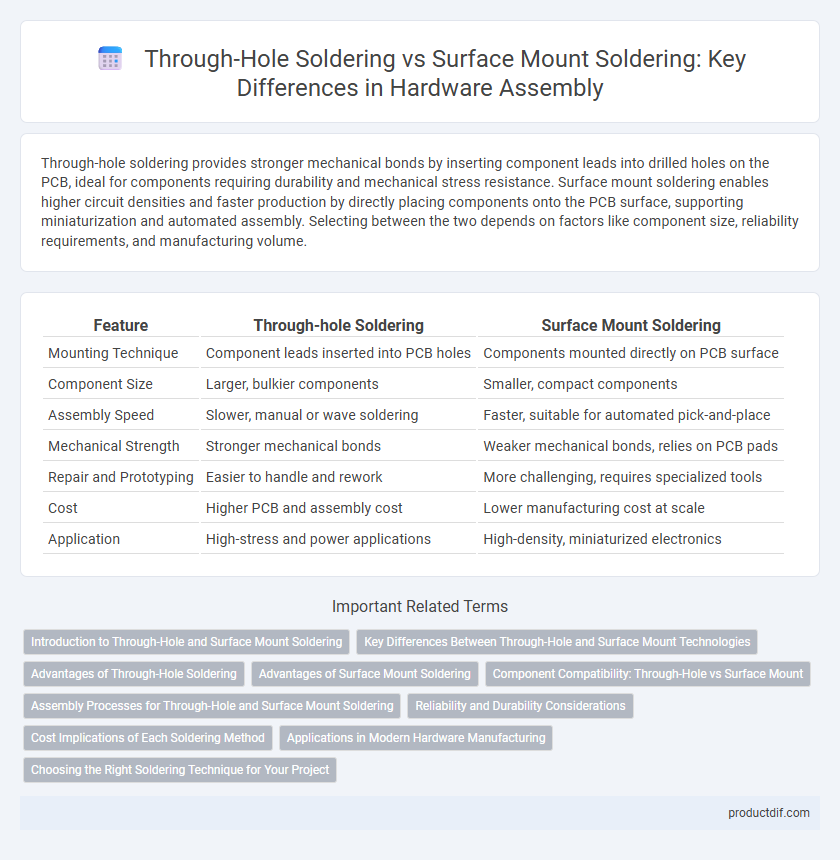
Table of Comparison
| Feature | Through-hole Soldering | Surface Mount Soldering |
|---|---|---|
| Mounting Technique | Component leads inserted into PCB holes | Components mounted directly on PCB surface |
| Component Size | Larger, bulkier components | Smaller, compact components |
| Assembly Speed | Slower, manual or wave soldering | Faster, suitable for automated pick-and-place |
| Mechanical Strength | Stronger mechanical bonds | Weaker mechanical bonds, relies on PCB pads |
| Repair and Prototyping | Easier to handle and rework | More challenging, requires specialized tools |
| Cost | Higher PCB and assembly cost | Lower manufacturing cost at scale |
| Application | High-stress and power applications | High-density, miniaturized electronics |
Introduction to Through-Hole and Surface Mount Soldering
Through-hole soldering involves inserting component leads into pre-drilled holes on a printed circuit board (PCB) and soldering them on the opposite side, providing strong mechanical bonds ideal for components subject to mechanical stress. Surface mount soldering attaches components directly onto the PCB surface pads without drilling, allowing higher component density and compact designs essential for modern electronics. Both techniques play critical roles in electronics manufacturing, with through-hole favored for durability and surface mount preferred for miniaturization and automated assembly.
Key Differences Between Through-Hole and Surface Mount Technologies
Through-hole soldering involves inserting component leads through drilled holes on the PCB and soldering them on the opposite side, providing strong mechanical bonds ideal for heavy or high-stress components. Surface mount technology (SMT) places components directly onto the PCB surface, enabling higher component density, faster assembly, and suitability for automated production. Key differences include assembly speed, component size, mechanical strength, and manufacturing cost, with through-hole favored for durability and SMT for miniaturization and mass production.
Advantages of Through-Hole Soldering
Through-hole soldering offers superior mechanical strength, making it ideal for components exposed to physical stress or heavy loads. It provides robust and reliable connections by inserting leads through plated holes, ensuring enhanced durability and easier inspection. This method also facilitates prototyping and manual assembly due to its straightforward process and strong joint integrity.
Advantages of Surface Mount Soldering
Surface mount soldering offers significant advantages including higher component density, enabling more complex and compact circuit designs. It provides faster production rates and better automation compatibility, reducing manufacturing costs and improving consistency. Enhanced electrical performance and lower parasitic inductance contribute to improved device reliability and speed.
Component Compatibility: Through-Hole vs Surface Mount
Through-hole soldering is compatible with larger and more mechanically robust components, making it ideal for connectors, transformers, and components subject to mechanical stress. Surface mount soldering supports smaller, lightweight components such as resistors, capacitors, and integrated circuits, enabling higher circuit densities and automated assembly processes. Component compatibility depends on design requirements, with through-hole favored for durability and surface mount preferred for miniaturization and mass production.
Assembly Processes for Through-Hole and Surface Mount Soldering
Through-hole soldering involves inserting component leads into drilled holes on the PCB, followed by wave or manual soldering, providing strong mechanical bonds ideal for heavy or high-stress components. Surface mount soldering uses automated placement machines to position components directly on PCB pads, with reflow soldering applying controlled heat to melt solder paste and secure components efficiently in high-volume production. Both processes require precise temperature control and solder paste application to ensure reliable electrical connections and minimize defects in assembly.
Reliability and Durability Considerations
Through-hole soldering provides enhanced mechanical strength and durability due to the lead wires passing through the PCB, making it ideal for components exposed to physical stress or high vibration environments. Surface mount soldering offers superior electrical performance and is better suited for high-density circuits but may exhibit lower mechanical robustness under mechanical shock or thermal cycling. Reliability assessments often favor through-hole for long-term durability in rugged applications, while surface mount technology is preferred in compact, precise electronic designs with controlled operating conditions.
Cost Implications of Each Soldering Method
Through-hole soldering generally incurs higher labor and manufacturing costs due to its manual process and increased material usage, including larger components and more solder. Surface mount soldering offers cost efficiency with automated placement and reduced material consumption, enabling higher production speeds and lower overall expenses. Choosing between these methods depends on factors such as production volume, component size, and assembly complexity affecting the total cost of manufacturing.
Applications in Modern Hardware Manufacturing
Through-hole soldering is preferred in applications requiring strong mechanical bonds and ease of prototyping, especially in connectors and larger components on circuit boards. Surface mount soldering dominates modern hardware manufacturing due to its compatibility with automated assembly processes, higher component density, and reduced board size, making it ideal for smartphones, laptops, and IoT devices. The choice between these techniques impacts production speed, cost efficiency, and the overall reliability of electronic products.
Choosing the Right Soldering Technique for Your Project
Choosing the right soldering technique depends on factors such as component size, circuit complexity, and production volume. Through-hole soldering offers strong mechanical bonds and is ideal for larger components and prototypes, while surface mount soldering allows for higher component density and automation in mass production. Evaluating these criteria ensures optimal reliability, assembly speed, and cost-efficiency for your hardware project.
Through-hole Soldering vs Surface Mount Soldering Infographic