Pin headers and socket connectors serve complementary roles in hardware design, enabling secure and flexible electrical connections. Pin headers consist of male pins that insert into socket connectors, which house female contacts, ensuring strong mechanical and electrical interfacing between components like PCBs and modules. Choosing between pin headers and socket connectors depends on factors such as ease of installation, durability, and the need for frequent disconnections.
Table of Comparison
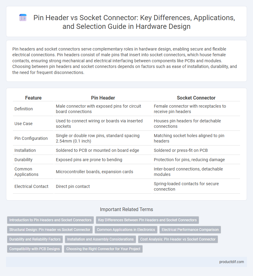
| Feature | Pin Header | Socket Connector |
|---|---|---|
| Definition | Male connector with exposed pins for circuit board connections | Female connector with receptacles to receive pin headers |
| Use Case | Used to connect wiring or boards via inserted sockets | Houses pin headers for detachable connections |
| Pin Configuration | Single or double row pins, standard spacing 2.54mm (0.1 inch) | Matching socket holes aligned to pin headers |
| Installation | Soldered to PCB or mounted on board edge | Soldered or press-fit on PCB |
| Durability | Exposed pins are prone to bending | Protection for pins, reducing damage |
| Common Applications | Microcontroller boards, expansion cards | Inter-board connections, detachable modules |
| Electrical Contact | Direct pin contact | Spring-loaded contacts for secure connection |
Introduction to Pin Headers and Socket Connectors
Pin headers are compact electrical connectors composed of one or more rows of metal pins used to establish simple, reliable connections on printed circuit boards (PCBs). Socket connectors feature corresponding receptacles designed to receive pin headers, enabling secure, removable connections between electronic components or modules. Both pin headers and socket connectors are essential for modular design and prototyping in hardware development, facilitating easy assembly and disassembly.
Key Differences Between Pin Headers and Socket Connectors
Pin headers are male connectors with exposed metal pins designed to be inserted into socket connectors, which are female counterparts featuring receptacles that securely house the pins. Key differences include pin headers offering straightforward, rigid connections suited for PCB mounting, while socket connectors provide flexibility and ease of replacement in modular designs. Compatibility with voltage ratings, pin pitch, and mechanical robustness are critical factors distinguishing the two in hardware applications.
Structural Design: Pin Header vs Socket Connector
Pin headers feature rigid, protruding metal pins arranged in single or dual rows for direct insertion into printed circuit boards (PCBs), providing mechanical stability and ease of soldering. Socket connectors consist of receptacles with spring-loaded contacts designed to securely hold pin headers, offering flexibility for repeated connection and disconnection without wear. The structural design difference impacts durability, with pin headers optimized for fixed, robust installations and socket connectors suited for modular or replaceable assemblies.
Common Applications in Electronics
Pin headers are commonly used in printed circuit boards (PCBs) for establishing secure and detachable electrical connections, especially in prototyping and development kits. Socket connectors find frequent applications in integrated circuit (IC) packaging and microcontroller boards to facilitate easy insertion and replacement of components. Both connectors play critical roles in modular electronic designs, enabling flexibility and efficient maintenance in devices such as computers, robotics, and embedded systems.
Electrical Performance Comparison
Pin headers provide a reliable, low-resistance contact ideal for high-frequency signal transmission, ensuring minimal signal loss and crosstalk. Socket connectors offer enhanced mechanical durability and maintain consistent contact pressure, reducing contact resistance variations over time and under vibration conditions. Both types vary in insertion loss and impedance stability, with pin headers excelling in fixed, soldered connections and socket connectors preferred for flexible, repeatable mating cycles.
Durability and Reliability Factors
Pin headers typically offer higher durability due to their rigid metal pins that resist bending and maintain consistent electrical contact under repeated use. Socket connectors provide reliable connections by accommodating slight misalignments and reducing mechanical stress through their spring-loaded contacts, which enhance lifespan in vibration-prone environments. Selecting between pin headers and socket connectors should consider operating conditions, as pin headers excel in stable, static assemblies while socket connectors perform better in dynamic, frequently connected interfaces.
Installation and Assembly Considerations
Pin headers simplify installation with their straightforward soldering to PCBs, offering reliable mechanical stability and electrical connections. Socket connectors provide easier assembly flexibility by enabling removable connections without soldering, ideal for modular designs and maintenance. Evaluating the need for permanence versus serviceability guides the choice between soldered pin headers and socket connectors during hardware assembly.
Cost Analysis: Pin Header vs Socket Connector
Pin headers typically offer a lower cost solution due to simpler manufacturing processes and fewer materials, making them ideal for budget-sensitive projects or bulk production. Socket connectors, while more expensive, provide enhanced durability and ease of maintenance by allowing repeated connections without wear on the PCB pins. Evaluating total cost of ownership should account for initial purchase price, assembly complexity, and potential replacement frequency in hardware design.
Compatibility with PCB Designs
Pin headers and socket connectors offer distinct advantages in PCB design compatibility by providing versatile interconnection options; pin headers are typically used for permanent soldered connections, ensuring a stable and compact footprint, while socket connectors allow for removable interfaces, facilitating modularity and easy maintenance. The choice between these components depends on the desired electrical and mechanical reliability, with pin headers suited for fixed setups and socket connectors ideal for prototyping or components requiring frequent replacement. Optimizing PCB layouts to accommodate pin pitch, connector orientation, and board thickness enhances overall system integration and performance.
Choosing the Right Connector for Your Project
Selecting the appropriate connector between pin headers and socket connectors depends on your project's electrical and mechanical requirements. Pin headers offer a compact, robust solution ideal for permanent connections and simpler assembly, while socket connectors provide flexibility for frequent plugging and unplugging, ensuring easy maintenance and component replacement. Assessing factors such as current rating, connection durability, and ease of troubleshooting will help optimize performance and reliability in your hardware design.
Pin Header vs Socket Connector Infographic