A logic analyzer captures and displays multiple digital signals simultaneously, making it ideal for debugging complex digital circuits and protocols. Oscilloscopes primarily measure analog signals with high resolution and are best suited for observing voltage changes over time in electronic components. Choosing between the two depends on whether the focus is on analyzing digital logic states or visualizing detailed waveform characteristics.
Table of Comparison
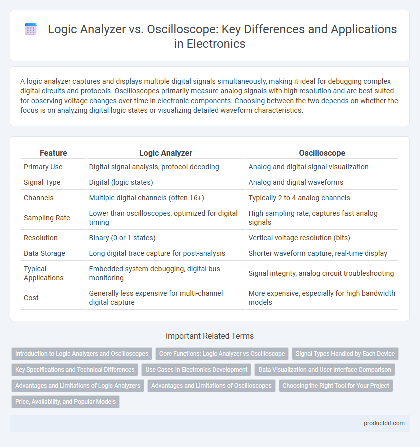
| Feature | Logic Analyzer | Oscilloscope |
|---|---|---|
| Primary Use | Digital signal analysis, protocol decoding | Analog and digital signal visualization |
| Signal Type | Digital (logic states) | Analog and digital waveforms |
| Channels | Multiple digital channels (often 16+) | Typically 2 to 4 analog channels |
| Sampling Rate | Lower than oscilloscopes, optimized for digital timing | High sampling rate, captures fast analog signals |
| Resolution | Binary (0 or 1 states) | Vertical voltage resolution (bits) |
| Data Storage | Long digital trace capture for post-analysis | Shorter waveform capture, real-time display |
| Typical Applications | Embedded system debugging, digital bus monitoring | Signal integrity, analog circuit troubleshooting |
| Cost | Generally less expensive for multi-channel digital capture | More expensive, especially for high bandwidth models |
Introduction to Logic Analyzers and Oscilloscopes
Logic analyzers capture and display multiple digital signals simultaneously, providing detailed timing analysis for complex digital circuits. Oscilloscopes measure and visualize analog signals with high time resolution, making them ideal for observing waveform characteristics and signal integrity. Both tools are essential for diagnosing electronic systems but serve different testing purposes within circuit design and debugging.
Core Functions: Logic Analyzer vs Oscilloscope
A logic analyzer captures and decodes multiple digital signals simultaneously, providing detailed timing relationships and protocol analysis critical for debugging complex embedded systems. An oscilloscope measures and visualizes analog voltage waveforms over time, enabling precise observation of signal amplitude, frequency, and noise characteristics. While oscilloscopes excel at waveform analysis and signal integrity testing, logic analyzers specialize in examining digital logic states and timing across numerous channels.
Signal Types Handled by Each Device
Logic analyzers excel in handling digital signals by capturing and analyzing multiple channels simultaneously, making them ideal for debugging complex digital circuits and protocols such as SPI, I2C, and UART. Oscilloscopes are versatile tools designed to measure and visualize analog signals, providing detailed waveform analysis of voltage over time, including frequency, amplitude, and noise characteristics. While oscilloscopes can also display digital signals, their primary strength lies in analog signal diagnostics, whereas logic analyzers specialize in timing and logic state analysis in digital domains.
Key Specifications and Technical Differences
Logic analyzers capture and analyze multiple digital signals simultaneously, offering high channel counts typically ranging from 16 to 1,024 with sampling rates up to several gigahertz, ideal for debugging complex digital circuits. Oscilloscopes provide detailed real-time waveform visualization of analog signals with bandwidths from a few MHz to several GHz and sample rates often reaching tens of gigasamples per second, crucial for signal integrity and timing analysis. Unlike oscilloscopes, logic analyzers lack analog measurement capabilities but excel in capturing long-duration digital data patterns and protocol decoding, making each tool essential for specific diagnostic tasks in electronics.
Use Cases in Electronics Development
Logic analyzers excel in debugging complex digital circuits by capturing and analyzing multiple signal channels simultaneously, making them ideal for timing verification, protocol analysis, and state machine debugging. Oscilloscopes provide real-time visualization of analog waveforms, enabling detailed examination of signal integrity, noise, and transient events critical for analog and mixed-signal circuit development. Electronics engineers often use oscilloscopes for hardware validation and signal troubleshooting, while logic analyzers are preferred for software-hardware interaction analysis and digital communication debugging.
Data Visualization and User Interface Comparison
Logic analyzers offer advanced data visualization by capturing and displaying multiple digital signals over time, enabling detailed timing analysis and protocol decoding, while oscilloscopes primarily focus on continuous analog waveform visualization. The user interface of logic analyzers often includes customizable timing diagrams and state sequence views that facilitate digital troubleshooting, whereas oscilloscopes provide intuitive controls and real-time waveform adjustments suited for analog signal inspection. Both tools integrate graphical displays, but logic analyzers prioritize digital event correlation and multi-channel timing precision, contrasting with oscilloscopes' emphasis on signal amplitude and frequency examination.
Advantages and Limitations of Logic Analyzers
Logic analyzers excel in capturing and analyzing complex digital signals across multiple channels simultaneously, offering detailed timing and state information ideal for debugging digital circuits and communication protocols. They have limitations in bandwidth and cannot capture analog signal variations like oscilloscopes, which visualize continuous waveform changes in real-time. Logic analyzers require digital inputs and specialized setup, making them less effective for analog troubleshooting or simple signal monitoring tasks.
Advantages and Limitations of Oscilloscopes
Oscilloscopes provide real-time visualization of electrical signals, allowing detailed analysis of waveform shape, frequency, and amplitude, which is essential for troubleshooting analog circuits. They offer high bandwidth and fast sampling rates, enabling the capture of transient events and signal anomalies with precision. However, oscilloscopes are limited in analyzing complex digital protocols and long-duration signal sequences, areas where logic analyzers excel due to their protocol decoding and extensive timing capture capabilities.
Choosing the Right Tool for Your Project
A logic analyzer excels at capturing and analyzing multiple digital signals simultaneously, making it ideal for debugging complex digital circuits and communication protocols. Oscilloscopes provide detailed waveform visualization for both analog and digital signals, crucial for measuring signal integrity and timing in analog electronics. Selecting the right tool depends on your project requirements: use a logic analyzer for in-depth digital signal timing and state analysis, while an oscilloscope suits analog signal diagnostics and waveform inspection.
Price, Availability, and Popular Models
Logic analyzers typically have higher price points than oscilloscopes, reflecting their specialized digital signal analysis capabilities, with popular models including the Saleae Logic Pro 16 and the Agilent 16902A. Oscilloscopes are generally more affordable and widely available, favored for their analog and mixed-signal testing, with leading models such as the Rigol DS1054Z and Tektronix TBS2000 series dominating the market. Both instruments are crucial in electronics diagnostics, but budget-conscious engineers often prioritize oscilloscopes due to their versatility and cost-effectiveness.
Logic Analyzer vs Oscilloscope Infographic