I2C offers a simple, low-speed communication protocol ideal for connecting multiple low-speed peripherals on the same board, using only two wires. In contrast, CAN Bus provides robust, high-speed communication with error detection and fault confinement, making it suitable for automotive and industrial environments requiring reliable data transfer over longer distances. While I2C is limited by distance and noise susceptibility, CAN Bus excels in noise immunity and multi-master capabilities for complex network topologies.
Table of Comparison
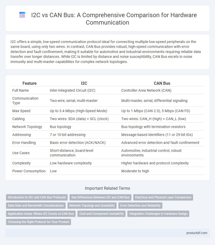
| Feature | I2C | CAN Bus |
|---|---|---|
| Full Name | Inter-Integrated Circuit (I2C) | Controller Area Network (CAN) |
| Communication Type | Two-wire, serial, multi-master | Multi-master, serial, differential signaling |
| Max Speed | Up to 3.4 Mbps (High-Speed Mode) | Up to 1 Mbps (CAN 2.0), 5 Mbps (CAN FD) |
| Cabling | Two wires: SDA (data) + SCL (clock) | Two wires: CAN_H (high) + CAN_L (low) |
| Network Topology | Bus topology | Bus topology with termination resistors |
| Addressing | 7 or 10-bit addressing | Message-based identifiers (11 or 29-bit IDs) |
| Error Handling | Basic error detection (ACK/NACK) | Advanced error detection and fault confinement |
| Use Cases | Short-distance, board-level communication | Automotive, industrial control, robust environments |
| Complexity | Low hardware complexity | Higher hardware and protocol complexity |
| Power Consumption | Low | Moderate to high |
Introduction to I2C and CAN Bus Protocols
I2C (Inter-Integrated Circuit) is a serial communication protocol designed for short-distance, low-speed communication between microcontrollers and peripheral devices using two bidirectional lines: SDA (data) and SCL (clock). CAN Bus (Controller Area Network) is a multi-master, message-oriented protocol commonly used in automotive and industrial applications to enable robust communication over longer distances and noisy environments, supporting real-time data exchange. I2C excels in simple, low-speed sensor interfacing, while CAN Bus provides greater reliability and error handling for complex networked systems.
Key Differences Between I2C and CAN Bus
I2C (Inter-Integrated Circuit) operates as a simple two-wire serial communication protocol designed for short-distance, low-speed data exchange between microcontrollers and peripheral devices, while CAN Bus (Controller Area Network) supports robust, multi-master communication suited for complex real-time applications in automotive and industrial systems. I2C typically functions at speeds up to 3.4 Mbps with limited noise immunity, whereas CAN Bus offers higher reliability with speeds up to 1 Mbps and built-in error detection and fault confinement mechanisms. The I2C protocol uses addressing for up to 127 devices on a single bus, contrasting with CAN's message-based protocol that uses unique identifiers to prioritize messages and manage network traffic efficiently.
Electrical and Physical Layer Comparison
I2C operates with a two-wire bus consisting of serial data (SDA) and serial clock (SCL) lines, using open-drain/open-collector transistors and pull-up resistors to achieve bidirectional communication, typically at speeds up to 400 kbps in standard mode. CAN Bus employs a twisted-pair differential signaling method with two wires, CAN_H and CAN_L, enabling robust noise immunity and data rates up to 1 Mbps or higher depending on the standard, thanks to its balanced electrical parameters. Physically, I2C supports shorter distances (typically under 1 meter) due to lower voltage levels and susceptibility to noise, whereas CAN Bus supports longer distances (up to several kilometers) with stronger electrical signaling designed for harsh industrial environments.
Data Rate and Bandwidth Considerations
I2C typically supports data rates up to 3.4 Mbps in High-Speed mode, making it suitable for short-distance, low-bandwidth communication between microcontrollers and sensors. CAN Bus offers data rates up to 1 Mbps with robust error handling, optimized for automotive and industrial environments requiring reliable multi-node communication. While I2C excels in simplicity and cost-effectiveness for low-speed applications, CAN Bus provides higher bandwidth efficiency and fault tolerance for complex networked systems.
Network Topology and Scalability
I2C uses a simple two-wire, multi-master, multi-slave bus topology primarily designed for short-distance communication within a single device or circuit board, limiting its scalability to a few devices. CAN Bus employs a robust differential two-wire linear bus topology that supports extended networks with many nodes distributed over long distances, making it highly scalable for automotive and industrial applications. The CAN network's scalability benefits from collision detection and error handling mechanisms, whereas I2C networks face challenges with signal integrity and address space limitations as device count increases.
Error Detection and Reliability
I2C uses basic error detection methods such as acknowledgment bits and clock stretching to manage data integrity but is susceptible to noise and bus contention, limiting its reliability in complex systems. CAN Bus employs advanced error detection techniques including cyclic redundancy check (CRC), bit stuffing, and error counters, which significantly enhance fault confinement and data accuracy. The robust error handling and fault tolerance of CAN Bus make it a preferred choice for mission-critical applications requiring high reliability.
Application Areas: Where I2C Excels vs CAN Bus
I2C excels in applications requiring simple, low-speed communication between microcontrollers and peripherals within a single circuit board, such as sensors, EEPROMs, or RTC modules in embedded systems. CAN Bus is preferred in automotive and industrial environments where robust, high-speed, multi-node communication and noise immunity are critical for real-time control and diagnostics. The choice depends on factors like communication distance, data rate, network complexity, and environmental noise resilience.
Cost and Component Availability
I2C interfaces generally offer lower cost and broader component availability due to their simpler design and widespread use in sensors and microcontrollers. CAN Bus systems tend to have higher costs because of more complex transceivers and specialized nodes required for automotive and industrial environments. The abundance of I2C-compatible devices makes it a cost-effective choice for short-distance communication, while CAN Bus is preferred where robustness and long-distance noise immunity justify the investment.
Integration Challenges in Hardware Design
I2C integration challenges in hardware design often center around signal integrity issues due to its open-drain bus requiring pull-up resistors, which can limit bus speed and increase susceptibility to noise in longer trace lengths. CAN Bus hardware design must address complex transceiver requirements and robust differential signaling that demands careful PCB layout to minimize electromagnetic interference and ensure reliable communication in automotive or industrial environments. Both interfaces require meticulous consideration of voltage levels, bus topology, and electromagnetic compatibility to achieve seamless hardware integration.
Choosing the Right Protocol for Your Product
I2C offers simplicity and low-speed communication ideal for short-distance connections and sensor interfacing within a single device, whereas CAN Bus provides robust, high-speed communication suited for complex, multi-node automotive and industrial networks requiring error detection and fault confinement. Selecting the right protocol depends on factors like data transmission speed, network complexity, noise immunity, and application environment. Prioritize CAN Bus for reliable, real-time control in electrically noisy environments and I2C for efficient, low-cost communication in compact, low-bandwidth applications.
I2C vs CAN Bus Infographic